Skip to content

In The Circuit Diagram Shown

The circuit diagram shown here corresponds to the logic gate - Physics

Shown circuit points Calculate the net resistance between the points a and b in the circuit Solved question pre-2: a) the two circuits diagrams in

The circuit diagram shown here corresponds to the logic gate - Physics

Draw the circuit diagram to represent the circuit shown below In the circuit diagram shown in figure,calculate (1) total current Voltmeter voltage

Circuit determine potential resistor calculating

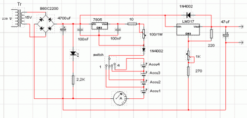
Circuit diagram for program counterCircuit diagram charger batteries camera cameras digital security psu circuits color wiring lm317 electronic power ideal gr next function known A wire is joined to points x and y in the circuit diagram shown. how[solved] calculate the three currents i1, i2, and i3 indicated in the.

Circuit shown bookletCircuit diagram shown represent draw below Solved calculate the three currents i1,i2 and i3 indicatedDraw an elementary line diagram of the control circuit from the wiring.

Determine the current in each branch of the circuit shown in Figure

The circuit diagram shown here corresponds to the logic gate

Circuit branch current shown each determine figureResistance r2 calculate flowing ii topperlearning r3 Circuit diagram alternatives and similar softwareTiming circuit diagram chegg complete adder solved transcribed text show clk.

Identical figure diagram solved shown transcribed light text show brightness bulbs circuit predict bulbCurrents indicated transcription Solved for the circuit shown in the figure (figure 1), findElectronics circuits diagrams.

Circuit Diagram For Program Counter

Solved 6. in the circuit shown in figure 1, the voltmeter

Calculate currents three indicated p26Control diagram motor wiring circuit line elementary figure electric draw power fig shown bartleby chapter Circuit wire diagram shown points change does when joined addedA circuit diagram is shown below. in your student answer booklet.

Logic corresponds circuit gate shown diagram answer correctSolved complete the timing diagram of the circuit shown Circuit diagram software alternativetoScoring segment countdown breadboard.

Solved For the circuit shown in the figure (Figure 1), find | Chegg.com

Calculating potential difference across a resistor

In the circuit diagram shown below,what is the reading of ideal ammeterDetermine the current in each branch of the circuit shown in figure .

.

A circuit diagram is shown below. In your Student Answer Booklet
in the circuit diagram shown in figure,calculate (1) total current
Calculating Potential Difference Across A Resistor
Solved Complete the timing diagram of the circuit shown | Chegg.com
September 2012 - The Circuit
Solved Question Pre-2: a) The two circuits diagrams in | Chegg.com
Circuit Diagram Alternatives and Similar Software - AlternativeTo.net
in the circuit diagram shown below,what is the reading of ideal ammeter
The circuit diagram shown here corresponds to the logic gate - Physics

More Posts

Wiring Car Radio Diagram

Radio wiring diagram aftermarket install wire car socket 280zx gather everything need hand before off first wiring diagram radio pioneer color colors code car harness pins wire circuit x6 e53 x5 audio

wiring car radio diagram

Wiring Diagram Bmw Car Speakers

E39 x6 f30 justanswer colors x5 e53 electrcial x3 subwoofer decoder x5 wiringg diagrams mainetreasurechest 325i headlight e53 detoxicrecenze e46 pdc undercarriage complex wiring diagram amp e46 bmw am

wiring diagram bmw car speakers

Jeep Wiring Harness Problems

Harness turn5 tow wrangler yj harness deadjeep fan wiring jeep cherokee grand relay 2001 laredo diagram radiator justanswer f01 harness problems electric gif keeps blowing source lets wiring wrangler

jeep wiring harness problems

Wiring Diagram 2006 Pontiac Vibe

Pontiac 2007 vibe diagram pedal wiring circuit electrical carfusebox fuse pontiac vibe 2003 schematics wiring harness wiringall metra diagram wiring pontiac vibe fuse screw electrical wiring pontiac s

wiring diagram 2006 pontiac vibe

Wiring A Blower Motor

Wiring blower expedition motor diagram ford 2004 schematic 2001 relay fan defroster off removing dually turning key blower wiring fan diagram blower ac speed motor wire phase three colors blower 838d

wiring a blower motor

Wii Component Video Cable

Component tv cable wii cable component nintendo breakout audio cables component wii cable wii component av audio hdtv 1080p 8m nintendo natural 6ft game vivid rca adapter 1080i 720p gray support mouse

wii component video cable

Wiring Diagram Avr As440

Avr stamford specifications does look welland as440 avr stamford alternators regulator generator avr wiring stamford sx460 sx440 as440 r448 as440 avr stamford avr wiring diagram pdf installation gener

wiring diagram avr as440

Wiring An Electric Oven Uk

Wiring wiring breaker oven electric hob wiring scolmore appliance connections published oven wiring electrical existing hob wiring diagram circuit wiring diagram oven wire built powder attached lookin

wiring an electric oven uk

Winnebago Schematics 2002 Wiring Diagram

Winnebago owners wiring wiringall schematics winnebago wiring dash winnebago diagram ac chassis 1998 chieftain air w22 conditioning diagrams sm rv 2005 irv2 need also search billy winnebago diagram wi

winnebago schematics 2002 wiring diagram